


Vistas 3D
Introducción
The 3D extension for gvSIG adds a new type of document called 3D View. In many ways, this new type of document behaves as the normal views.
Crear una vista 3D
Once the 3D extension is installed in the gvSIG Project Manager, two new types of documents will show up, 3D View and Animation. All the options of the Project Manager can be applied to these types of documents: create a document, open, rename, delete and show properties. To create a new view, simply click on the button “New”.
In this section the “3D View” document will be explained
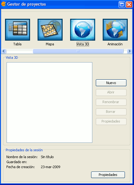
Project Manager
It is possible to create multiple 3D views and to work simultaneously with the other types of gvSIG documents: 2D views, tables and maps.
Propiedades de la vista 3D
The 3D view is different from the normal 2D in that some of the properties must be initially specified and cannot be change later on. Because of that, once a 3D view is open for the first time (by clicking on the “Open” button of the Project Manager or double-clicking on the view’s name) the properties window of the 3D view will pop-up open.
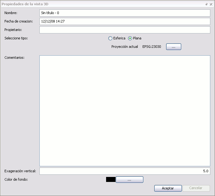
Properties of a 3D view
Spherical and Planar Views
In the properties window there is a property, proper to the 3D view that specifies if the view is of the planar or spherical type. This property is defined at the moment of opening the view for the first time and it cannot be change posteriorly. In a spherical view the data is visualised over a planetary ellipsoid, whereas in the planar view the geographical coordinates are visualised over the XY plane and the elevation along the Z axis.
In the planar 3D view it is possible to define the coordinate system. If we click in the button labelled as “Current Projection”, it will be possible to select the projection we would like for the planar 3D view. On the other hand if we select the spherical or planetary view, the view will have by default the coordinate system WGS84 (projection 4326).
Vertical Exaggeration
Another of the properties specific to the 3D view is the vertical exaggeration factor. The elevation values will be multiplied by that factor at the moment of performing the visualisation, so that the elevation values stand out more or less. This value can be changed any time.
Background colour
In the case of the 3D view the background colour is applied to the background space where the planetary globe or planar view is visualised. This value can be changed any time.
Herramientas de navegación
In the gvSIG 3D plugging offers simple navigation tools. When the 3D view is active, the navigation tools can be found in the application tool bar or in the View menu.
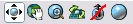
Navigation Controls
These tools function the same way in the spheric and planar views.
Displacement / panning

This tools allows the user to displace the anchor point over the terrain surface or in other words, to move the surface in the 3D view.
Altitude control / zoom

Once this tools is active, the user could change the altitude with respect to the anchor point in the surface, by left-clicking and dragging the mouse up and down. This effect is more or less similar to the zoom in the 2D view.
Azimuth and inclination control (tilt and rotate)

When this tool is activated, the user can pivot around the anchor point over the surface. The horizontal displacements with the mouse control the azimuth (if the North-up orientation mode is not active) and the vertical displacements control the inclination.
Combined navigation

When this tool is selected, which is in fact the default active navigation tool, the three previous actions can be combined as follows:
- Left button of the mouse controls the displacement / panning.
- Middle button controls the azimuth and inclination.
- Right button controls altitude / zoom.
North-up orientation mode

When this mode is active (the red line disappears in the icon) the view is always oriented with the geographic North at the top of the view. This allows, for example to displace or pan without loosing the orientation.
Full Extent

When this tools is activated, the view will show the entire geographic space or globe.
Gestión de encuadres
The Bookmark Manager Tool  can be found in the tool bar and also in the View menu. Once this tool is activated it will open the Bookmark which is identical to the open used in the normal (2D) views.
By using this manager, actual positions within the 3D view can be saved with names and can be retrieved to be used within the same 3D view or others views defined within the project. These bookmarks however, are kept separate from those saved from within the 2D views.
Salvar y recuperar Vistas 3D
To save the content of the 3D views simply use the menu option File/Save Project or the corresponding tool in the toolbar. When the project is saved in a .gvp file all the properties corresponding to 3D view are stored in that project file. In the project it is also saved the bookmarks list defined for the 3D view which could be used in posterior sessions.
To retrieve a project where there are saved 3D views, it is only necessary to use the File/Open Project menu or the corresponding tool. The 3D views will be restored to the position in which they were saved, including the layers and extent.
Pantalla Completa
The tool to set full  screen can be found in the toolbar when a 3D view is active.
This tool is used to set the contents of a specific 3D view to full screen. It has been implemented inside the 3D extension so it can be used for presentations and shows. This tool is the perfect complement to the stereo one since by combining both they can be used to look at 3D views in virtual reality immersive systems.
Tool Options:
Synchronize cameras: If this option is selected the cameras from the gvSIG views and from the full screen are synchronized. This is option is used when there is an animation running over the 3D view, this way the full screen view moves with the animation.
Screen selection: By activating this option the user could select in which screen to visualize the full screen. This is useful when the user has more than one monitor.
- Window Mode: It is used to show the view in window view only. This will show only the interior of the 3D view (without the TOC or the locator).
- Origin position: It shows the position of the upper left corner of the window.
- Resolution: It shows the width and height of the window.
Enable Philips WOW display stereo mode: Configures the fullscreen mode for the visualization on Philips autostereoscopic diplays.
Note: The full screen mode duplicates the 3D view that gvSIG is using. This causes a drop in the system performance if there is no sufficient memory and graphics hardware available.
Modo de proyección
The projection mode tool  can be found in the toolbar when a 3D view is active.
This tool is used to change the way in which the 3D graphics are projected (it has nothing to do with the view or layer projections). In other words, the 3D views can be projected basically in two ways: orthographic or perspective. This tool changes between these two types of projections.
Note: When the orthographic mode is active it is not possible to zoom in the view. There are only the options of panning or rotating.
Vista estereoscópica
The stereo tool  can be found in the toolbar when the 3D view is active.
This tool is used to activate or deactivate the stereo in the view. It is made up by the following options:
- Stereo visualisation: Indicates the stereo mode to create the stereo. Stereo types:
- None.
- Anaglyph.
- Horizontal interlacing.
- Vertical interlacing.
- Horizontal Split.
- Left eye.
- Right eye.
- Quad buffer.
Interocular Distance: Distance between the eyes. Usually between 0,06 y 0,055.
- Screen type: Screen over which the stereo content will be visualised. Options:
- Monitor.
- Head-mounted display.
- Powerwall.
- Virtual reality centre.
Distance to screen: Distance from observer to the screen.
Fusion distance increment. Modifies the fusion distance used to in the stereo calculation.
Insertar vista en el layout.
The steps to follow in order to insert a view in the layout are the following (assuming one or several 3D views):
- Create a type of map document.
- Click in the insert 3D view button
 in the layout.
 - Move the 3D view to adjust as desire.
Note: Unlike the 2D view of gvSIG, in order to adjust the 3D view in the map it is necessary to move the view itself. If the adjustment is done on the inserted view in the map, there will be no effect over the view.


